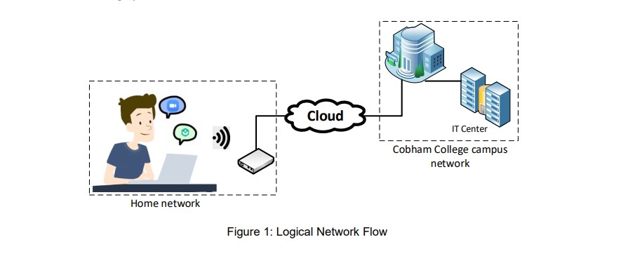
The OSI Model layers are typically described from the top layer down. The layers are described as Application, Presentation, Session, Transport, Network, Data link and Physical layer. In this section we are going to explain how the data travels from the student computer to access the OnlineLearning system server in Cobham College IT Center.
Student’s/Lecturer’s computer >
Ø 7
- Application layer
The application layer
interacts directly with the user's data and recognize it, such as the student.
The data of the student will travel from their computer to the server of the
OnlineLearning system. Software applications like the internet browser are used
to initiate communication with the user in order to access the system. The software used clearly does not fall into
this layer. Application layer only responsible for protocols and data handling
for the software being used.
Ø 6
- Presentation Layer
Presentation layer mainly responsible
for preparing the data for use by the application layer. This means that this
layer is in charge of the translation, encryption and compression of the data.
All data entered by the student, such as username and password, will be changed
into a bit stream before being transmitted. Encryption
will be added to student data so they can protect the confidentiality of their
data. So finally, the Presentation layer will compress the data to reduce the
number of bits in the data to improve the speed and effectiveness of
communication.
Ø 5 - Session layer
In the Session layer, the
construction, direction and conclusion of connection between devices occur.
Which in this case are the Student computer and OnlineLearning system server.
After the connection is established, the data then passes to or from the
transport layer.
Ø 4 - Transport layer
It is responsible for the
transmission of data across network connections. This layer will coordinate how
much data is the student sending and how fast and where it could goes.
Transport layer will do flow control for inter network communication, so the
flow can determine the most optimal speed for data transmission to make sure
that the sender (student) has fast connection, so the OnlineLearning system server
then will not be overwhelmed with slow connection. Once transport layer has
completed its function, the data is then passed to or from the network layer.
Ø 3 - Network layer
It handles the routing of the data,
routing is finding the best physical path for student data to reach OnlineLearning
System server in the Cobham College IT Center.
Ø 2 - Data link layer
This layer is often divided into
sublayers called media access control (MAC) and logical link control (LLC). The
layer sets up links across the physical network. When data link layer receives
data from the physical layer, it checks for transmission errors and then
packages the bits into data frames. At the data link layer, the data passes to
or from the final layer which is the physical layer.
Ø 1 - Physical layer
This layer encompasses the network
cables, power plugs, etc. Student data that has been passed down from previous
layer will be convert into signals and transmit over local media.
OnlineLearning System server >
Ø 7
- Application Layer
The OnlineLearning system server will
perform as a website that stores all resources related to the educational
purpose such as images, videos and files. The server will respond with the
required content.

Ø 6
- Presentation Layer
The data transmitted to the server is
encrypted. Thus, the presentation layer will be responsible for decoding these
data in order for them to be readable and for the receiving device that is the
server to understand them. However, this layer will also translate the data
into the language that the application layer of OnlineLearning system server in
the Cobham College IT Center can understand.

Ø 5
- Session Layer
After all the data from the students
computer has fully exchanged to OnlineLearning system server, The communication
session between both devices will be close to prevent wasting resources.

Ø 4
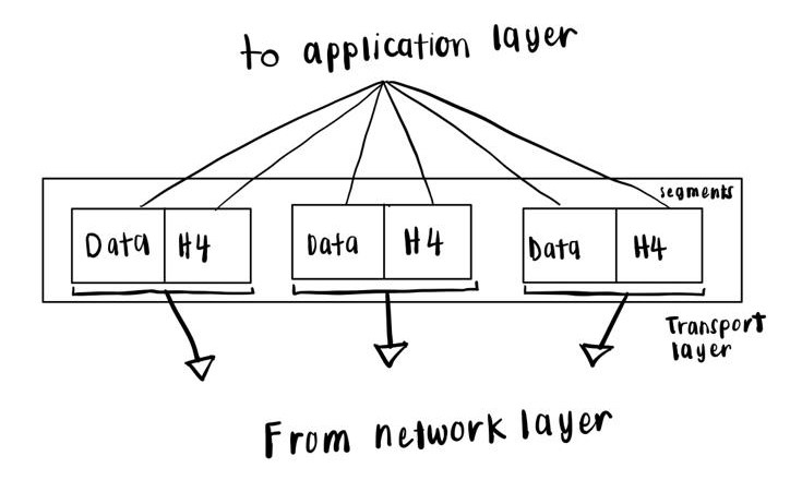
- Transport Layer
In the transport layer for the user's computer, the data decomposed into bits called segments. So then the segment will be aggregated to data that the session layer can consume.
Ø 3
- Network Layer
For the network layer of the server, the small data units known as packets will be reassembled into segments which will be used on the transport layer.
Ø 2
- Data Link Layer
The received frame of the physical layer will be reassembled in two packages and then transferred to the network layer.
Ø 1
- Physical Layer
The physical layer will receive the signal and convert it into bits and switch it to the Data Link layer as a frame.

Comments
Post a Comment